Contents
This project contains 240V wiring. 240V can kill you. I take no responsibility if you kill yourself, blow your house up etc etc. Proceed at your own risk. This project involves some metal / wood work, use of a soldering iron, and optional programming :)
This is what I used, broken down into what parts came from what.
If you don't use the driver boards on the floppy disk drives, you can make your own. See below.
First I'll apologize for the pics, they were taken with a Sony Handycam which isn't really good for stills. And they were taken after I'd finished building most of it, which meant I had to take the thing apart to get pictures.
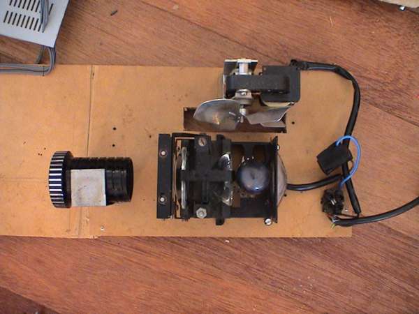
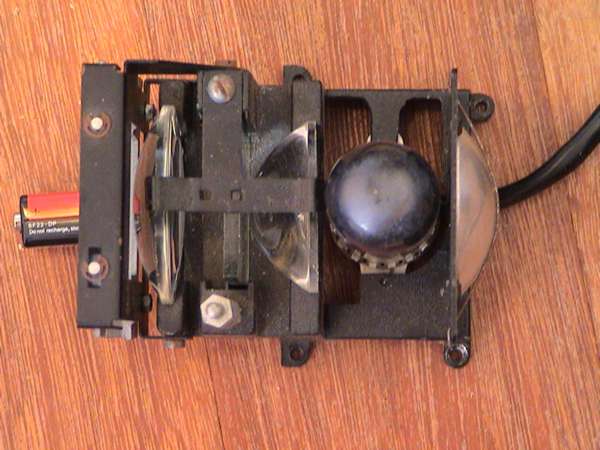
Pull the lens assembly out of the projector, mine came in two parts, the bulb and lenses, and the focusing lens as shown below.
Cut a piece of wood for the base, I used 16mm MDF, 250 x 550 mm to start with and cut it down to size when I was done. Mount the bulb assembly and focusing lens on it. The projector that I used came with a fan which I used as well.
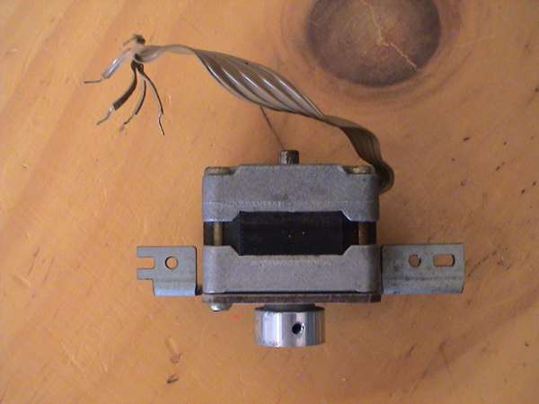
Next up is to remove the stepper motors from the floppy drives. Get to work with a screwdriver and they come apart pretty quickly. If you intend using the driver PCB, make sure you don't snap them :).
The stepper motors have discs on the axle which can be a pain to remove. Sometimes they have a small screw which, when undone releases it. If there is no screw or once undone it still won't come off you have two options: i) saw the bastard off with a hacksaw (bad if you end up cutting the axle) ii) heat the disc somehow and it just pops off (I used a small blowtorch thing). I used method i first and ended up almost cutting the axle in half, so I've switched to method ii from now on.
The next part is to work out the order of the poles. (Go read the reference section on how stepper motors work). Stepper motors in floppy drives seem to have 5 or 6 wires. Here are two colour schemes I've come across:
| Wire | Colour | Colour |
|---|---|---|
| Ground | Brown x 2 | Black |
| 1 | Red | Brown |
| 2 | Blue | White |
| 3 | White | Red |
| 4 | Yellow | Green |
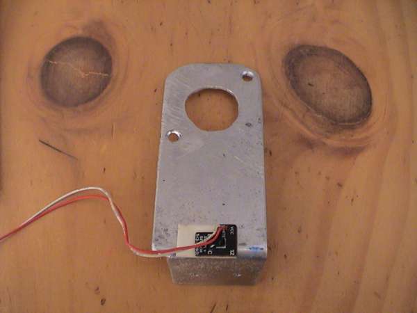
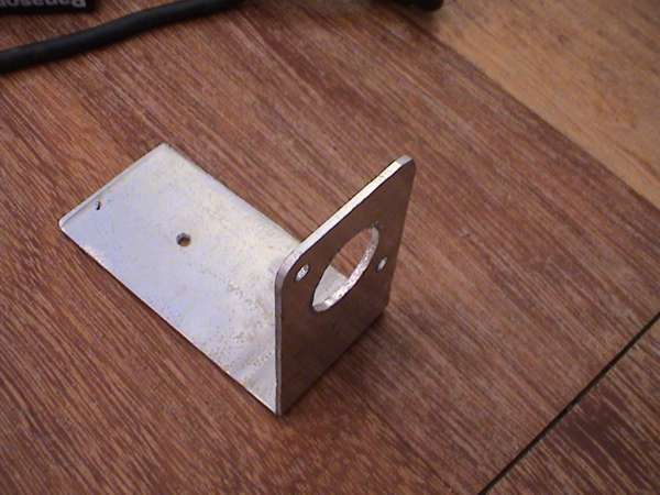
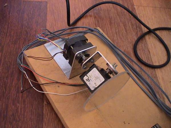
Next up is to make the brackets for the motor(s). These are pretty easy, cut a strip of metal ( I used 1mm think aluminum). Drill holes for the motor and cut a circular section out so it fits well. File off all the sharp edges.
Ignore the black thing at the bottom, its a infrared detector, see the updates section for more info. The reason that there is a slice cut out the bottom of this bracket is so it fits around the focusing lens.
You need to make one bracket for the color wheel, and one for the mirror. Only bend them once you've worked out the height they need to be (later).
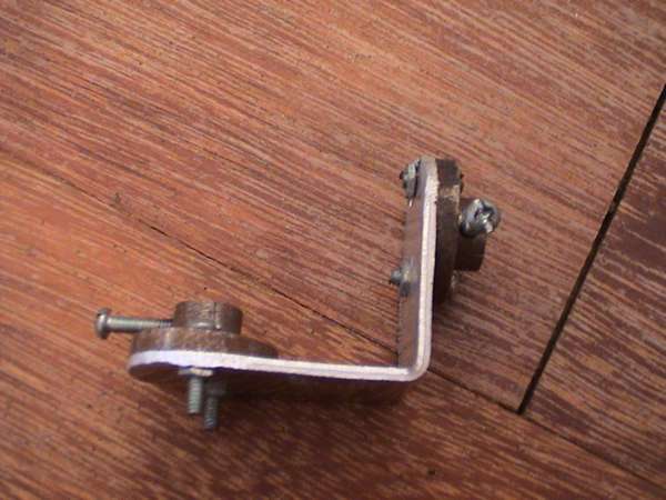
Ok, this is probably the hardest part, you need to make small discs that fit over the axles of the stepper motors, and allow them to be attached perpendicularly to a surface (you can see one in the photo of the colour wheel below). I used a metal lathe at my old school to do this, I doubt I would have been able to make them otherwise. Start with a solid circular length of metal and cut it down to size. The dimensions are hardly important. Once you have the right shape, drill a hole through the center for the motor axle. Then use a drill press for the tightening bolt (the vertical one below) and the other two. The hole for the tightening bolt has to have a thread cut into it else the bolt won't stay in place. Use plenty of oil and go slowly else you'll break the cutting bit (I did).
You need three of these discs in total.

Next make to colour wheel, I used the metal in the base of the VCR for mine. The circle needs to be a big as possible but kept within the size of the case. Mine had a diameter of 100mm. The diameter of the inner circle was about 45mm (the same width as the body of the stepper motor) which leaves just under 30mm as the width of the segment. I cut 5 segments out each with an angle of 45 degrees. The gaps between the segments were 20 degrees , which leaves 55 degrees for a 'blacked out' segment.
I got the colour gels from my old school's theater arts department. Don't use cellophane, it will melt with the heat. The gels were attached with bolts as shown above.
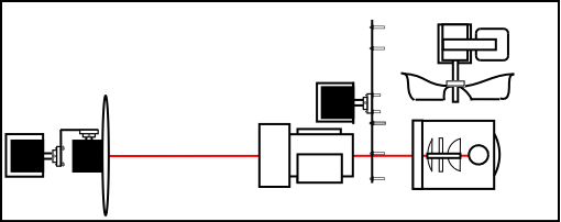
Next mount the colour wheel in place on the base board. It needs as much colour possible covering the focusing lens.
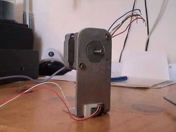
Onto the main part. Make another bracket for the motor to support the mirror like so:
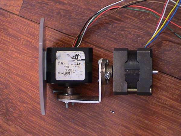
Note the base does not need to be this long. I was just being lazy and later chopped it down to size. Next you need a small bracket to go between the first and second motors. Try to center the mass of the second motor on the axis of the first. This will reduce the force required by the first motor, which is a good thing :)
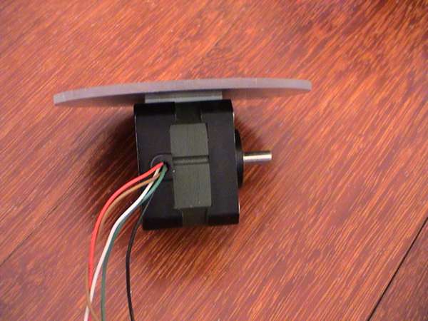
Cut out a circular piece of mirror. Mine was 90mm in diameter. Plastic mirror is MUCH easier to work with. Glue (or use double sided tape) to attach the mirror to one of the motors as shown:
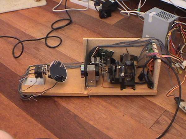
Them put the whole thing together and you should get something like this:
Now use the bracket and attach to the base board. The mirror needs to be lined up dead center with the beam of light to get the best effect.
Ok, now we're about half way through. That's most of the mechanical work out the way, onto the electrical bits:
Finally take some more sheet metal, and use it to create a slide for the projector. Cut any pattern you want, I used 3 circles in a triangle formation. These are called gobos in the theater industry.
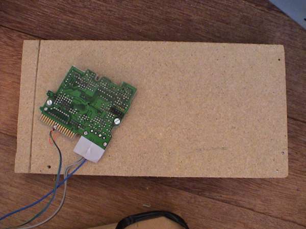
If you want to use to driver PCBs from the disk drives you need to connect them as so.
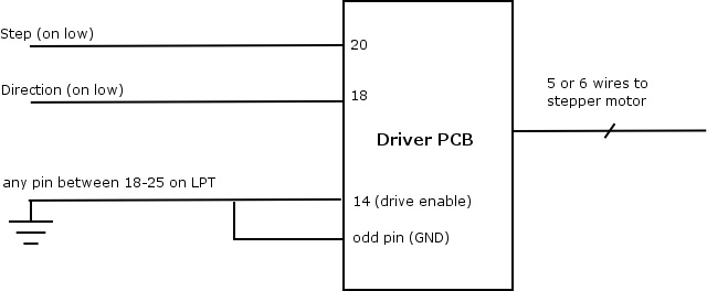
Be warned though that the driver PCB's have an annoying habit of performing a full rotation when power was applied (this was supposed to reset the head in the disk drive). There is a IR detector that stops the rotation when the beam is cut built into the driver circuits, mine didn't seem to work too well. It didn't really matter as I prefer to build my own driver circuits (see updates).
If you decided not to use the driver PCBs, you need to make drive circuits for each stepper. The following circuit works well (from Aaron's site).
For those interested, the above is a finite state machine with 4 states and outputs 1010, 1001, 0101, 0110 (pins 15,14,1,2). This means you should connect the stepper motor wires in order to 15,2,14,1
For a power supply I used a AT power supply out an old PC. Use the +5 (red) , +12 (yellow) and ground (black) wires.
The parallel port terminals we're interested in are:
| Pin No. | Normal Use | Our Use |
|---|---|---|
| 2 | Data 0 | Direction X |
| 3 | Data 1 | Step X |
| 4 | Data 2 | Direction Y |
| 5 | Data 3 | Step Y |
| 6 | Data 4 | Direction Z |
| 7 | Data 5 | Step Z |
| 10 | Ack | Colour Wheel Sensor |
| 18-25 | Ground | Ground |
So build the circuit up, I used standard strip board. I suppose if you're hardcore you could etch your own PCBs.
The easiest way to control the light is through the parallel port on a PC. I wrote a number of C programs to do this under linux: fx.c. This acts as a small interpreter and allows me to create sequences etc.
Some sequence files:
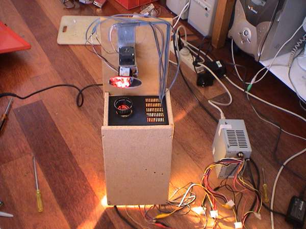
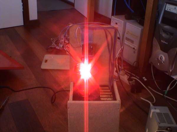
If you've got this far, its time for a test, wire the beast up and give it a whirl.
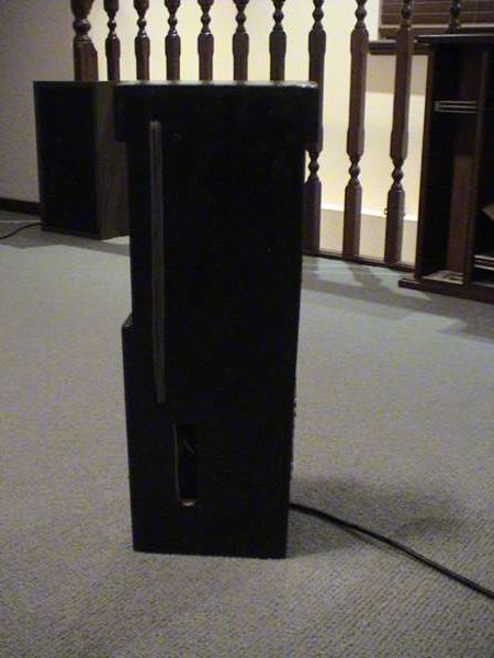
Last thing to do is to clean it up a bit. I built an enclosure for the top motor to hide all the wiring. Counter sink all the screws, sand the edges smooth, route a groove in the back of the base board to carry the wires to the steppers. Finally give it a coat of black paint.
There were a couple of issues I wasn't happy with. The first was the movement was rather slow and jerky. Changing the C code with an oscilloscope attached to the parallel port allowed me to tweak it so this jerkiness disappeared.
By removing the second nanosleep call in the for loop significantly increased the speed. The problem was that running at 5V, the motors could not keep up and ended up just vibrating on the spot. The solution was to increase the operating voltage to 12V but it meant I could not use the driver PCB out the disk drives. So I built a third driver circuit and all works well.
Another problem that became apparent was the need for some sort of feedback on the position of colour wheel. I pulled the Infrared LED and detector out the VCR and modified the colour wheel so that one part was longer than the other (see pic). Then I made the following circuit. Use a variable resistor for R1 to adjust the sensitivity, once you've found a good operating point you can solder one on (I think I used about 80k).

One problem with the detector is that when the light it on, it swamps the output of the LED and renders the detector useless. This is ok though because you only need to know where the wheel is once (assuming it doesn't slip). So with the light turned off, run the init.c program, the turn the light on and your set to go.
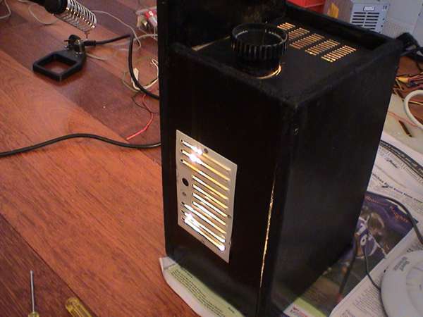
Once everything was completed, I gave it a burn in test. It quickly became apparent that with a 300W bulb, good airflow was required. The stepper motor driving the colour wheel got too hot to touch, and began missing steps at high speed. I cut a hole in the side closest the bulb and put the grate from the projector over it to stop too much light escaping. Now the air is flowing straight across the bulb and I haven't had anymore problems even after running continuously for 6 hours.

Decide where to mount the power supply. I suppose I should really buy a +12,+5 V transformer instead of using the computer PSU. This could be mounted in the case, although it would get quite hot with the heat. A solution would have been to create a separate compartment in the case for the electronics and transformer and seal this off from the compartment with the bulb in.
Build a new driver circuit to do half stepping. This will increase the resolution of the motors, giving more control over the movement.
Use another output pin on the parallel port to turn the light on and off. I need to hook up a 240V relay for this.
Buy one of those small PC's on a chip so I can do away with the computer or for about the same price I could buy a microprocessor and development board use that.
Somehow (and that is a big somehow) use the sound card and a microphone to detect beats in the music, and use this to trigger the speed of the light and colour changes. As yet I have no idea how to do this :( .
 This is now working (albeit not for this light) with ArtNetController
Build a second light, they always look better in pairs :) Then build a circuit to allow them to be switched in and out of phase with each other.
Look at swapping to a halogen light to try and reduce the amount of heat. The current bulb also wastes a lot of light.
The first time I intended to use this was a Bevan's 21st. At the time the laptop I was using didn't have a hard drive, so I had to boot DamnSmallLinux of a CD, and copy the binaries and sequence files across a network (too old for usb, floppy drive doesn't work). Anyway I fully charged the battery, booted it, copied the files, then raced into the car and Brett sped all the way to Bevan's (pizza delivery experience comes in handy :). Anyway we got there without killing ourselves and the battery was on 3/4 so I plugged it in to the mains and went to say hi to everyone. About 10 mins later I get back to set it up and the piece of crap has decided to reboot and so I lost all the files. I was not very happy for the next few mins, but then I got over it and had an awesome night ;).
I did a test run at home later in the week when the parents went out (I've previously been 'banned' from using the fog machine in the house). Here is a short movie I took, the sound you can hear in the background is the smoke alarm going mental as well as DJ Jean's The Launch on the Ministry of Sound - Trance Classics album <--awesome 2 CDs.

Now I just have to wait for them to go away for the weekend again and it'll be sweeeeet :)